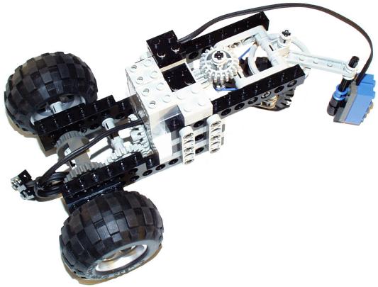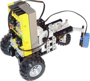
construction detail, RCX removed

I first built the front steering wheel using the large pulley as a base. It is attached to a crossaxle with a perpendicular connector. That makes a nice compact support without requiring any bracing. Turning the wheel with a pulley greatly simplifies the placement of the steering motor, since gear meshing isn't an issue.
After I attached the steering motor to some beams (using 1x2 plates with tabs) I realized that this whole assembly was going to have to be much higher than the rear section of the robot. It turns out that the beam spacing required for the crossbracing I planned was just large enough to attach the drive motor to the bottom beam directly beneath the steering motor. The bottom beam became the rear frame. The drive motor has a 24t crown gear which drives a 24t idler which drives the rear differential.

I tried several strategies:
Line edge following relies on the fact that the sensor sees the light as black, the surrounding area as white, and when positioned partway over the line it sees a shade of gray. You can always tell which way to steer because you either see too much line (black) or too much background (white).
Method 1 was fine tuned well enough that the steering didn't oscillate much at all. It could make clean turns to the edge of the line. Its dainty approach to turning was too slow to follow an abrupt curve and if it entered a curve too fast the robot would just go straight.
Method 2 is a vastly simplified version of 1: In most lighting conditions the white areas were in the 60s and the black areas were in the 30s. So a hardcoded target value of 50 was used and the robot sought it by steering at full speed. This is prone to repeatedly overshoot. It looks like it is scanning the edge of the line repeatedly. This method might work for wide black lines, but if they are narrow there is a risk that the overshoot will go completely over the line, especially when combining an oversteer in one direction as you enter a curve going the opposite direction. Net effect: same behavior as method 1!
I thought method 3 would be foolproof, but it isn't much better than method 2.
So for an RCX-based line follower, it is pretty fast. It could easily lap the testpad in about 10 seconds at greatly reduced drive power. What I wanted was to go MUCH faster, on the order of 3-4 seconds per lap, but my line following wasn't up to the challenge.
I still think fast line following is an interesting challenge, but it's going to be harder than I thought.